Heat pumps
Part 2
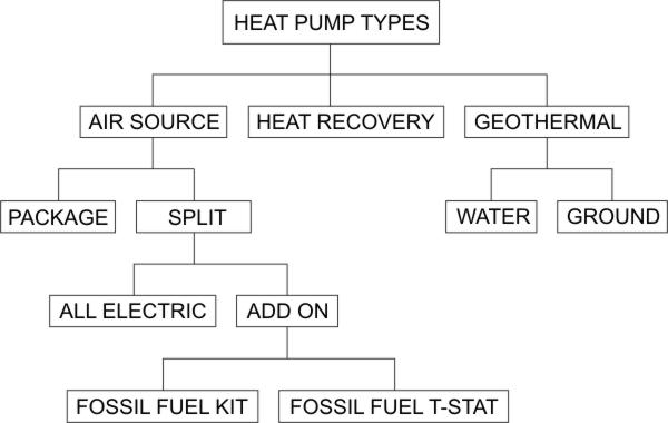
Air Source - Package Heat Pump

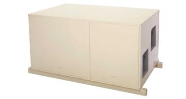
The photo shows a roof top package air source heat pump. All of the mechanical components are contained in the package. It requires ductwork, power and control wiring and a remote thermostat but the refrigerant side of the system is factory charged and ready to operate.

This system has 1 stage of mechanical cooling and 2 heating stages. The first heating stage is the heat pump mode. When auxiliary heat is needed, the 2nd stage heat (AUX) comes on automatically. The 2nd stage heat is electric resistance heating elements. The heat pump mode is typically about 3 times more energy efficient to operate than the AUX heat so the heat pump stage is always given the opportunity to try and satisfy the heating load by itself. If the heat pump mode can not keep up with the load the thermostat will call for 2nd stage heat to supplement the heat pump mode. In a package system the heat pump may run simultaneously with the AUX heat. This is allowable because the indoor coil (condenser in the heating mode) is upstream of the AUX heating elements. In other words the indoor coil can reject heat into the return air stream. It would not make sense to try and position the indoor coil downstream of the AUX heating elements because then it would be forced to try and reject heat into a heated airstream that might even be hotter than the coil.

When package heat pumps first became available there were no heat pump thermostats on the market. So the manufacturers designed units to work with standard multi-stage thermostats. Circuit boards and relays in the unit controlled mode switching via the 4-way reversing valve). This diagram shows a typical package heat pump control circuit with a standard multi-stage thermostat. On a call for 1st stage heat only heat pump mode is operational. If 2nd stage also calls both the heat pump mode and the AUX heat become operational. This is fine as the electric resistance heating elements are downstream of the indoor coil.
Click the buttons to see the 24 VAC control circuitry operating in the different modes.
Air Source - Split Heat Pump - Add On
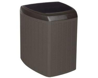
The photo shows the outdoor section of an air source split system 'Add On' heat pump. This means that the outdoor unit will be "added on" to a fossil fuel furnace. The system needs to be connected to an indoor coil with refrigeration piping. Control wiring will also be needed to connect the indoor unit, outdoor unit and the thermostat.
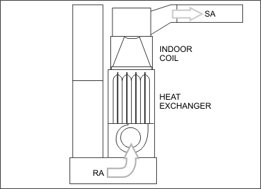
Since the indoor coil of an "all electric heat pump" can be located upstream of the electric heating elements there is no problem running the heat pump and the back up heating simultaneously. However, the "add on" heat pump must shut off every time back up heat is required. This is because an "add on" system's indoor coil must be located downstream of the fossil fuel heat exchanger. One might ask why not simply locate the indoor coil upstream of a heat exchanger and then one could have an "add on" heat pump that could also run back up heat simultaneously with the heat pump". The reason is a bit illusive. One must look to the cooling mode for the answer. If the indoor coil was upstream of a heat exchanger, then the heat exchanger would become quite chilled by the evaporator outlet air during the air conditioning mode. Humidity could condense on the heat exchanger which would promote corrosion and possibly rot out the heat exchanger. Leaks are not allowable in fossil fuel heat exchangers because combustion products contain CO (Carbon Monoxide) which is poisonous. Since the heat exchanger is located in the air stream supplying the conditioned space, codes do not allow such an arrangement.

One method of controlling an Add ON heat pump system is to use a "Fossil Fuel T-Stat".  Conventional multi-stage T-Stats and even normal
heat pump T-Stats allow simultaneous calls on both heating stages. A special type of heat pump T-Stat called a "Fossil Fuel T-Stat" must be used. This type of T-Stat drops out the first stage heat (Y or compressor) whenever
the 2nd stage heat calls (W or AUX). However, whenever the system goes into defrost mode no defrost tempering takes place and cold air is distributed throughout the conditioned space for the entire duration of the defrost.
Standard colour coding for field wiring heat pump control circuits is:
R red 24 VAC
G green FAN
Y yellow COOL
W white HEAT
O orange 4-WAY
C black COMMON
Click the buttons to see the 24 VAC control circuitry operating in the different modes.
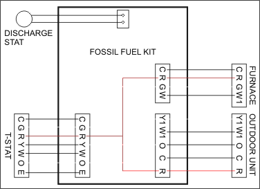
Another option is to use a "Fossil Fuel Kit"  . This control system also keeps the 2 heating stages from running simultaneously with some
specific exceptions. It utilizes a "Plenum Thermostat" to sense the discharge air temperature of the heat exchanger and allows the gas furnace to run for short bursts during the defrost mode. This tempers or warms up the
cold supply air during defrost and creates more comfortable conditions. The "Fossil Fuel T-Stat" can not do that. It allows cold air to blow out of all of the registers for the entire duration of the defrost. The
"Fossil Fuel Kit" also allows for a slight overlap when AUX heat first calls. Instead of the 1st stage heat shutting down immediately it allows the heat pump to continue running for a short time but only until the
"Plenum Thermostat" senses that the temperature coming off of the heat exchanger is starting to become too warm. This slightly increases energy efficiency but over the life of the equipment makes a difference.
Click the buttons to see the 4 basic loop types.
Geothermal heat pumps relocate heat between the ground and a conditioned space. Below the surface, the Earth remains at a relatively constant temperature throughout the year, warmer than the air above it during the winter and cooler in the summer. Air source heat pumps lose efficiency as the outdoor air temperature drops. The COP of an air source heat pump can drop from a 3:1 ratio right down to a 1:1 ratio in cold enough temperatures. There is no sense in operating an expensive air source heat pump when it's COP has dropped to that of electric resistance heat. However, a ground source heat pump is immune to low ambient conditions. It will maintain a relatively constant COP throughout the heating season and will be overall more efficient than an air source heat pump.

However, a GSHP is much more expensive to install than an air source system. This is primarily due to the cost of the loop. To consider a GSHP there must be sufficient land available and the composition and properties of the soil must be determined. Soil with good heat transfer properties can use a smaller loop to gather a certain amount of heat. In the winter, the fluid in the pipes extracts heat from the earth and carries it into the building. In the summer, the system reverses and takes heat from the building and deposits it to the cooler ground.
If a geographical location has a moderate heating season, GSFP's may not be able to compete with high efficiency air source heat pumps due to the significant difference in installation costs. On the other hand there are many locations with more severe heating seasons where air source heat pumps are not even a realistic option.
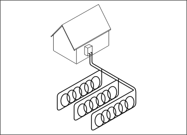
There are 4 basic types of geothermal loops. There are 3 closed loop and 1 open loop systems. The most common is the closed loop, in which high density polyethylene pipe is buried horizontally 4 to 6 feet deep or vertically at 100 to 400 feet deep. These pipes are filled with an environmentally friendly antifreeze/water heat transfer solution. Ground water can be used as a source for open-loop systems, provided the water quality is suitable and all ground water discharge regulations are met per local codes.
Click the buttons to see various types of geothermal loops.
Heat Recovery
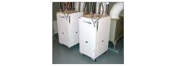
Water source heat pumps can be used for heat recovery applications.

Consider the case of an indoor shopping mall. There are stores and offices spread throughout the interior. Many have large quantities of display lighting and other equipment giving off heat. Some of the stores are in the core of the mall, others are located on the perimeter. This can cause differing heating and air conditioning demands. [MALL] Consider the cold winter season. The perimeter stores all share a portion of the outside wall and many of them may require heating. However, the stores located in the core of the building are surrounded by the conditioned space of the perimeter stores and are not subjected to a cold outside wall. They are still creating heat from lighting and can require air conditioning. [ZONES] There is a very energy efficient way to satisfy the variable heating and cooling loads of the individual stores. A large piping loop is built throughout the mall. [LOOP] This loop circulates a glycol/water solution. Water source heat pump Air Handling Units can then be added for each store, office or hallway location. [AHU's] It is much more energy efficient to relocate existing heat to other areas that need it rather than create it for each location that needs heat. If there are 100 stores each one can remove or add heat to the main loop to satisfy it's individual needs. It doesn't even matter where the store is located, each one can create it's own individual zone. If the main loop falls outside pre-determined parameters a large boiler and cooling tower can either add or remove heat to the loop to keep things in balance.
Click the buttons to follow the text.
Balance Point
The Balance Point of a heat pump is the outdoor temperature (typically around 30 °F at which a heat pump's output exactly equals the heating needs of the conditioned space. Below the balance point, supplementary heat is needed to maintain indoor design conditions.
COP
COP or Co-efficient Of Performance is a way of describing a heat pump's efficiency. It is the ratio of heat produced to the amount of energy required to run the system. The COP is calculated by dividing the total heating capacity provided by the heat pump, including circulating fan heat but excluding supplementary resistance heat (BTU's per hour), by the total electrical input (watts) x 3.412. Another rating given to heat pumps is HSPF. Typical COPs for an air source heat pump under optimum conditions are 3 to 1. In other words for one dollar's worth of energy input you receive 3 dollars worth of energy output. However conditions are not always optimum. As outdoor temperatures drop so does the COP. At a COP of 2:1 you would still be receiving twice the heat output compared to straight electric resistance heating elements. (if electric elements were rated by a COP, they would rate 1:1) No matter how cold it gets outside the COP of an air source heat pump never gets any worse than 1:1. However it is not wise to torture the expensive heat pump under these conditions when the same output efficiency can be achieved by other means. The annual energy savings attributable to a heat pump are a result of the sum totals of all the times the heat pump was operating with COP's greater than 1:1 during the entire heating season. Most of the energy savings occur in the milder portions of the heating season when little or no back up heat is required and the bulk of the heating requirements are being met primarily by the energy efficient heat pump.
Ground and Water Source Heat Pumps
It is possible to relocate heat from the ground or water with a heat pump. Both of those methods fall under the classification of geothermal. Most of the time ground and water temperatures are higher than winter air temperatures so they are more efficient to use as heat sources. For example there can be a raging snow storm with air temperatures in the 0 °F range yet the ground temperature 6 feet down might be 40 °F. However those mechanical systems are a lot more complicated than air source heat pumps and although COPs of 4:1 or higher can be achieved, the much greater installation costs and increased maintenance and repair costs should be carefully considered compared to the expected extra energy savings.
Airflow Requirements
It is important that the indoor air handler and duct distribution system are capable of moving an adequate quantity of air to satisfy the air flow requirements of the indoor coil when it is in the condenser mode. A typical rule of thumb for air flow requirements is 400 CFM per Ton (cubic feet per minute per Ton) for air conditioning systems and 450 CFM per Ton (cubic feet per minute per Ton) for heat pump systems. Inadequate condenser air causes high head pressures and temperatures which leads to compressor failures.