
25 to 30 millivolts
750 millivolts
 |
 |
| Thermocouple 25 to 30 millivolts |
Powerpile 750 millivolts |
 |
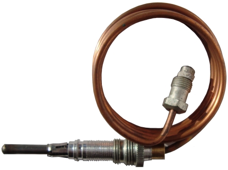
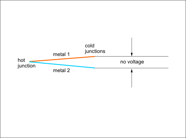
ThermocoupleStanding pilot systems rely on the pilot flame to ignite the main burner when the main gas valve opens. An appliance must not be allowed to open the main gas valve and let raw gas accumulate in the event of a pilot flame outage. The above devices, thermocouples and powerpiles, provide a fail safe mechanism for proving that the pilot flame has not been extinguished. The thermocouple is a thermal electric device which generates electricity when heated. Thermocouples are composed of 2 dissimilar metals which are bonded together at a junction point. These are typically iron and constantan for gas appliance thermocouples. If the junction point is subjected to heat, a small voltage is created in the range of 25 to 30 millivolts. This small voltage can be used by a gas valve as proof that the pilot flame has not been extinguished and that it is safe to allow the main gas to open when there is a call for heat. There are 1000 millivolts in 1 volt, so you can see that 30 mV is a very small amount of voltage. |
 |
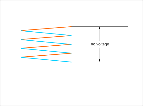
PowerpileA powerpile is composed of several thermocouples attached together in series. When subjected to heat, a much greater voltage is created in the range of 750 millivolts. It is easy to distinguish a powerpile from a thermocouple because it is bigger. Powerpiles create just enough voltage that a complete control system can be operated by the electricity generated by the pilot flame. The 0.75 of a volt can travel through thermostat wiring, through a T-Stat and back to a furnace and still have enough power to operate a gas valve coil. Both of these flame sensing devices should have their tips immersed into the pilot flame by about 1/2 inch to ensure adequate voltage output. |
 |
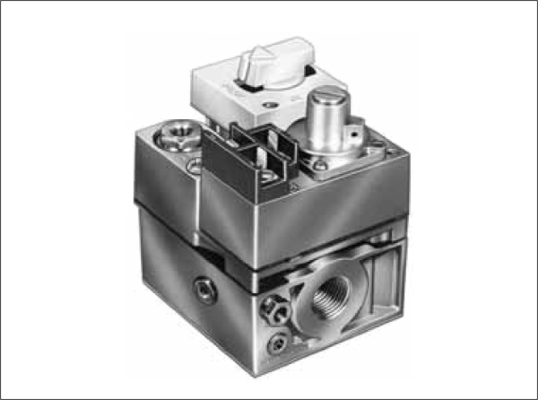
Combination Gas ValveThe image shows a combination gas valve. The valve has a built in regulator to reduce the 7 "wc gas pressure to the required 3.5 "wc. Examine the [Labels] and [Schematic] diagrams. Take note that the high temperature limit safety switch is in the high voltage circuit. If it opens, all power to the appliance is removed. The low voltage portion of the electrical schematic couldn't be any simpler. There is a single switching device (Thermostat) and a single load (gas valve coil). Unless the limit opens, any call from the T-Stat will energize the main coil in the gas valve. The [Wiring] button displays a typical manufacturers wiring diagram for the same circuit. The TH/TR terminal is just a dummy terminal that provides an easy location to connect together the thermostat and transformer wiring. Note the coil symbol between the lower two terminals. Click the camera to see a photo of a gas valve that is designed for use on automatic spark ignition systems. |

|
Flame SafeguardIt appears from the above schematic and wiring diagrams that the gas valve coil will be energized irrespective of whether the pilot is burning or not. This is indeed the case. Where then does the flame safeguard feature fit in? The answer is very simple and can be seen by clicking [Thermocouple] and [Labels]. Combination gas valves have two valve ports in series. If either one closes, no gas flow can occur. Compare [Off] and [Pilot On] to see the 30 mV circuit in action. Note that the 30 mV is not powerful enough to pull in the pilotstat coil. The pilot button or switch must be pushed in and held in place manually while the pilot is being lit and the thermocouple is heating up. Once the thermocouple is outputting sufficient voltage the manual button can be released and the pilotstat coil will be held in place by the thermocouple millivoltage. If the 24 VAC circuit calls for heat the main coil is energized and gas flows to the main burner and is ignited by the proven pilot. Should there be a pilot [Outage] it does not matter if the T-stat calls for heat and energizes the main coil. The millivolt circuit will have de-engergized the pilotstat, closing off gas flow to the main burner as well as the pilot burner. |