
 |
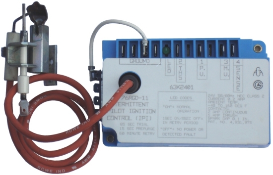
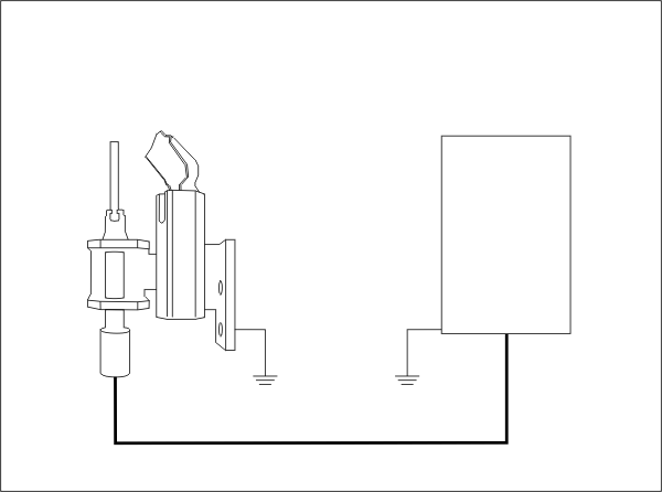
Flame RectificationA very common flame proving system in use today for residential and commercial heating systems is the flame rectification system. This system relys on the fact that a flame can conduct electricity. The [Diagram] to the left (and the above photograph) show an intermittent pilot control system. When the pilot flame is established it immediately conducts an electrical signal from the flame safeguard control through the flame and completes a circuit through ground back to the flame safeguard control. [Circuit] If there is a pilot outage, the signal is broken and the flame safeguard control immediately shuts off the pilot and main burner. Note the difference in the size of the flame rod to the size of the grounding area before going to the next section. [Area] |
 |
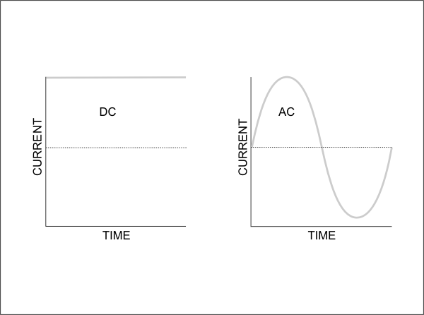
Rectification TheoryRefer to the diagram [Graph] and recall the difference between DC and AC power. This flame safeguard control uses a very small AC current in the 0.8 microamp range. Because there is a large difference in the size of the flame rod area compared to the size of the grounding area, more of the AC current passes through the flame in one direction than it does in the other. This results in a partial rectification of the AC current to DC current. [Rectify] The flame safeguard control recognizes this change to the flame signal and can instantly sense a flame failure and shut off the gas valve. There is no scenario where a rectified signal can return to the flame safeguard control unless the flame is established. This makes flame rectification an inherently fail safe system. |