Air Conditioning Control Basics
Foreword
How does one learn to troubleshoot HVAC equipment control circuits? Control circuits are composed of two primary components: switches and loads. Loads are devices such as: motors, heating elements, compressors and coils of contactors and relays. Load devices perform work. Even a compressor contactor is performing work. It takes work to hold in the contactor to maintain equipment operation. Switches turn things on and off. There are two main types of switches: safety switches and operating controls. Safety switches open circuits and turn off equipment if unsafe or undesirable limits are reached. They can be "normally open" or "normally closed". For example, an air proving switch in an induced draft gas heating system is normally open and only closes when adequate combustion air is provided by the induced draft blower assembly. Operating controls open and close circuits to cycle equipment on and off in order to maintain a condition. For example, a thermostat will cycle an air conditioner on and off to maintain a specified temperature within a conditioned space. Pressure safety switches will interrupt a control circuit and shut off an air conditioning system if excessively high or low refrigerant pressures are approached. Safety switches are therefore in series with operating controls. If either opens the equipment stops operating. Safety switches are designed to sense parameters such as pressure, temperature, amperage, voltage, smoke etc. Operating controls typically sense temperature and/or humidity.Control circuit designs range from very simple and straight forward to extremely complex. Complex functionality can be accomplished with multi contact contactors and relays. Multiple purposes can be accomplished simultaneously with relays with NO and NC contacts. For example, instead of leaving a crankcase heater permanently on. it can be wired through a NC contact on a compressor contactor. There is no need to keep it energized once the compressor is operating. The purpose of a crankcase heater is to stop liquid migration into the compressor sump during the off cycle. Once the compressor is operating, it creates enough heat to serve that function so the crankcase heater is no longer needed. In some designs, when the compressor contactor pulls in, a NC contact on the compressor contactor opens turning the crankcase heater off. Crankcase heaters are very low wattage so this may seem like a trivial energy saving idea but there are millions of crankcase heaters so the energy savings are actually significant. Besides, OEM's are always looking for ways to improve their equipment's SEER rating to remain competative. Other designs cycle crankcase heaters by a dedicated thermostat. Circuits can be designed with relays that are held in by their own contacts. There are holding circuits and lockout circuits and fuses and circuit breakers and transformers and solid state controls. Solid state or electronic control boards are used extensively in HVAC equipment. How then does one begin to learn to troubleshoot the vast number of control circuit design possibilities? An Ohm meter can measure if a component has electrical continuity and whether it is within an acceptable range. A volt meter can measure whether voltage is present and in an acceptable range. An Amp meter can do the same for amperage draw. But that is not going to be enough. First one needs to understand the purpose and functionality of a system. That is the purpose of this interactive ebook. It addresses the things one needs to know to learn to troubleshoot HVAC systems.
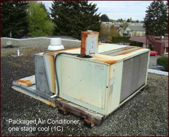
ACCB takes you on a journey exploring many types of air conditioning systems. Each type of equipment shown below has it's own section with an in depth study of its components, electrical schematic and operational modes. Every section has a review test which automatically marks answers. ACCB is intended as a supplement to Refrigeration Basics III. RBIII introduced basic principals and demonstrated the inter-dependency between the refrigerant, air/water and electrical sides of a system. ACCB was created for those who are interested in more controls training for air conditioning systems. ACCB introduces the feedback loop and then provides a review of electrical fundamentals, motors and starting gear. It demonstrates various types of thermostats including programmable and communicating set back T-Stats. The Electrical controls and Troubleshooting section delves into troubleshooting methods for individual components. Ultimately this leads to the amazing 100 interactive troubleshooting boards with built in faults. The boards allow the participant to develop HVAC troubleshooting skills with virtual test instruments by measuring electrical parameters (Volts, Ohms, Amps and Capacitance).
