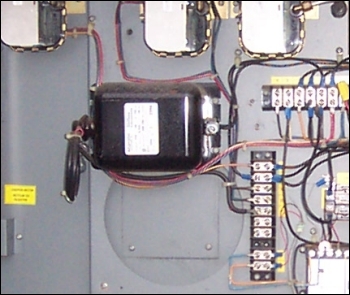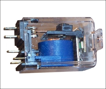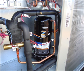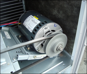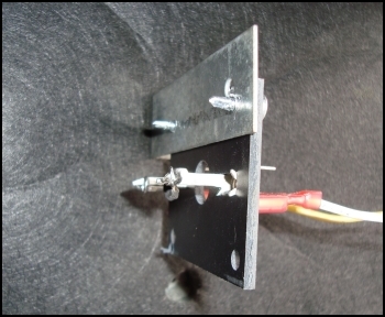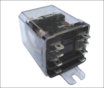
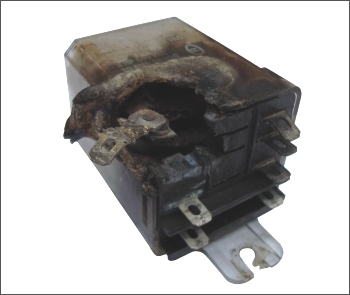
An HVAC system is designed to combust fuels or consume electrical energy to provide heating or cooling to a conditioned space. These systems must be controlled and made safe. Operating controls sense temperature and signal the system to operate or shut off and rest. Safety controls sense operating parameters and shut down the system if undesirable or unsafe conditions occur. The starting point for troubleshooting any system should be knowledge of what the system is and what it is supposed to do. One needs to know whether a particular component should be operating or energized or not operating or not energized. A window air conditioner has two moving parts; a compressor and a double shafted fan motor. When the control system calls, these two components need to operate. A two stage heat pump with two compressors, four outdoor fan motors, an indoor blower motor and two reversing valves is a different story. That system has a variety of operational modes; 2 stages of cooling, 2 stages of heat, a defrost mode, and a fan only mode. Specific combinations of components need to be energized and operating to facilitate the different modes of operation. Before beginning to troubleshoot it, one must know what components are supposed to be operating in each mode. It helps to know that a heat pump loses capacity as the ambient temperature drops. So heat is needed the most when it is the least available from the heat pumps. For this reason control systems are designed to combine both compressor stages as the first heating stage. Knowing this, if this system is operating in the heating mode and one of the two compressors is inoperative it should be obvious that there is a problem. A condenser fan motor should always be operating any time the compressor is operating. Or should it? If the system is equipped with a fan cycling control for low ambient operation then it's proper for the fan motor to cycle off and on during cold ambient conditions to maintain refrigerant head pressure. If the system is a heat pump then it is proper for the outdoor fan motor to be off during the defrost mode. System knowledge is very helpful when troubleshooting. Observation and attention to detail can also be very helpful when troubleshooting. The adjacent relay has had a catastrophic failure. While installed in the unit it may be difficult to notice. It may be obscured by wiring and other components but by being observant and noticing it visually just think for a moment how much electrical troubleshooting could be avoided by zeroing in on the problem area right away. If a V-Belt is chirping or squealing because it is worn or loose that's a signal that the airflow may be inadequate and coils may be frosting up, heat exchangers may be overheating and safety controls may be open. Paying attention to detail, even audibly, can help with troubleshooting. Dirty coils and blower wheels can affect airflow and cause safety controls to open. Burnt contacts, charred wiring, carbon spark residue and charred coil enclosures are more examples of things that can be noticed visually. It is a wise troubleshooting procedure to use your eyes and ears rather than assume that test instruments are the only route to a diagnosis. Think about what a system should be doing versus what it is actually doing. If a heat pump is iced up, why not look to see whether the 4 way reversing valve wiring plug has popped off of the valve coil or if the defrost sensor is properly attached to the appropriate end bend on the coil before even thinking about bringing out any test instruments. |
Schematic Diagram |
Wiring Diagram |
The above two diagrams are electrically identical. However, schematics show the logic behind an electrical circuit and allow a mechanic to understand the intended functions of the electrical components and how the components relate to each other. A wiring diagram on the other hand shows the physical wiring layout as in where wires are connected and allows a mechanic to trace specific circuits. Both types are a great aid to the mechanic who is diagnosing equipment. It is very helpful when manufacturers include both types with their equipment. However, often only one type is included. Wiring diagrams tend to be more pictorial and sometimes show the approximate relative positions of components. Schematics are also called "ladder schematics" due to their resemblance to the legs and rungs of a ladder. Electrical circuits are primarily composed of switches and loads. A switch cannot allow direct circuit between electrical legs. That would be a dead short attempting to allow infinite amperage flow which would trip breakers or blow fuses. A switching device must only allow flow through a circuit that contains an electrical load. Examples of loads are the relay coils, solenoid valve coils, motor windings and transformers windings. The resistance of a load is designed for a specific voltage. When the proper voltage is applied to a load there is a voltage drop through the load equal to the applied voltage. In other words, the coil of a relay used in a 24 VAC circuit must be rated for 24 VAC. The coil of a relay used in a 208 VAC circuit must be rated for 208 VAC. Buttons with black text are active on this online evaluation page. Buttons with red text are not. |
|
The symbols used on electrical diagrams usually have a pictorial relationship to the components function or shape. Compare [Components] and [Symbols]. The overload symbol indicates that in an overload condition this safety switch will pop open. The transformer symbol shows a primary and secondary winding and indications of a ferrous core. The round symbol used for a coil is also used for motors. The thermostat symbol is a basic switch symbol with a thermal element added. This indicates that the switch will open and close due to temperature changes. |
This image shows the various states that switches can have during "Normal" or power off conditions. N.O. stands for normally open, N.C. stands for normally closed. The symbols also indicate whether the switches close or open on a rise or fall. Consider the N.O. temperature switch at the lower left. You can see that the switch would close on a drop of temperature. That makes this switch a heating thermostat. When a conditioned space starts to drop in temperature the heating system calls for heat. The thermostat on the bottom right is conversely a cooling thermostat. You can examine a larger list of electrical symbols here: electrical symbols |
The main electrical components in HVAC equipment are fan motors, compressors and devices like gas valves and solenoid valves. All of these are electrical loads. A load is a component in a circuit that converts
electricity into light, heat, or mechanical motion. HVAC control systems also contain switches and other control devices. Some switching devices have load components such as the coils in a contactor or relay.
The two main types of switches are safety switches and operating switches. Examples of safety switches are high pressure switches, low pressure switches and limit switches. Examples of operating switches are thermostats
and fan cycling controls. The purpose of a safety switch is to shut down the equipment before undesirable or dangerous conditions occur. An operating switch turns things on or off in response to a call for some action
such as a need for heating or cooling. Another example is a fan cycling switch which cycles a condenser fan motor during low ambient conditions. There are also electronic control devices. Some perform a single function,
others are integrated controls capable of more than one function. Before electronic components were available, all functions in HVAC control systems were accomplished by electromechanical components. There are other
types of systems around such as pneumatic control systems. These are excellent for modulating control because it is easy to vary the amount of pneumatic output pressure in response to a varying demand. However this
type of system requires an air compressor and expensive modulating control components. It is therefore best suited for large commercial systems such as found in tall buildings. There are many large commercial buildings
that use pneumatic control systems. Over the years electronics have become an ever more prevalent component in HVAC systems. It's hard to find a modern air condtioning or heating system that doesn't use electronic
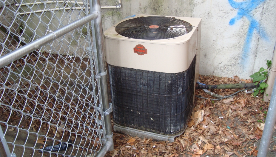
components. Consider this photo of an old condensing unit that was manufactured in the 1980's.
[ 1 ]
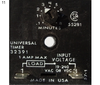
This air conditioning condensing unit was manufactured when electronics were just starting to be used the HVAC field. It has a single electronic component, an anti-short-cycling timer. Back then
mercury bulb T-Stats were the norm and people trying to make T-Stat temperature adjustments didn't realize that bouncing the mercury blob around was causing rapid starting and stopping of the equipment. This was of
course very bad for motors and compressors. So the anti-short-cycling timer was introduced. Sometimes a faulty component can be located by live troubleshooting. Often a faulty component is tentatively located by live troubleshooting and then it's condition is verified by taking test measurements while it is isolated from the circuit. Lets take a closer look at troubleshooting individual HVAC electrical components. |
Fuses |
Circuit Breakers |
Switches |
Capacitors |
Solenoid Valves |
Heaters |
Transformers |
Contactors & Starters |
Relays |
Compressors & Motors |
Temperature Sensors |
Miscellaneous |
Electronics |
Voltage Phase Imbalance |
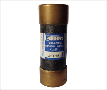
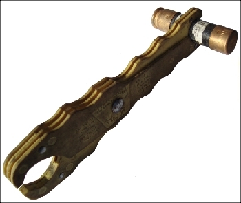
Fuses protect wiring systems. They are selected to protect wiring from an over amperage situation. If wiring or a component becomes grounded or shorted, the circuit would draw excessive amperage if not for the fact that the fuse would blow. If an oversized fuse is installed in a wiring circuit and a fault developed, it would allow more amperage flow than the wiring is capable of safely carrying. Under those circumstances the wiring could overheat and cause damage or even cause a fire. There are two main types of fuses: Quick Blow and Time Delay fuses. Time Delay fuses should always be used in a motor circuit. Motors draw a lot of amperage when they are first starting. Once they get up to proper speed the amperage draw should be less than the FLA rating on the equipment nameplate. If a Quick Blow fuse was used in a motor circuit it would likely fail. Time Delay fuses are marked with a TD. The only safe way to remove and replace a line voltage cartridge type fuse is with a fuse puller and with the power off. Blown fuses are usually located with a volt meter. When troubleshooting 3 phase power supplies it is good practice to remove the blown fuse and verify the fuses condition with an Ohm meter. |
||
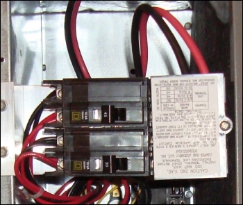
Circuit breakers protect wiring systems. They are selected to protect wiring from an over amperage situation. If wiring or a component becomes grounded or shorted, the circuit would draw excessive amperage if not for the fact that the circuit breaker would trip. If an oversized circuit breaker is installed in a wiring circuit and a fault developed, it would allow more amperage flow than the wiring is capable of safely carrying. Under those circumstances the wiring could overheat and cause damage or even cause a fire. Circuit breakers have a time delay, so they can be used in regular circuits as well as for motor circuits. There are also small circuit breakers that are used in control circuits and are sometimes built into control voltage transformers. They are available in single pole, two pole and three pole configurations. When used in 3 phase circuits they can be troubleshooted with a volt meter and an amp meter. A circuit breaker can wear out and become "lazy". It can trip and be reset and hold in for hours or days and then trip again. If no wiring or equipment faults can be found a breaker may have to be replaced to eliminate nuisance trips. |
||
Switches |
||
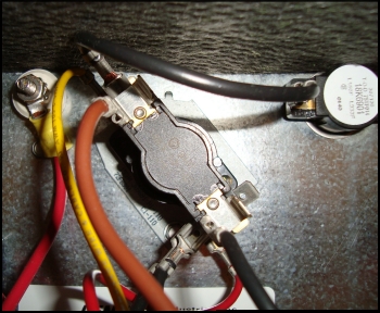
Switches are one of the easiest components to diagnose. They either have continuity or they do not. They are usually checked under live voltage with a volt meter. Switches that are NC can be tested for continuity when isolated from the circuit with an ohm meter. Switches can fail open or grounded. Some switches can only be checked for continuity when the power is on by using a volt meter. Consider for example a Fan Cycling Switch. It's a NO switch that will only close when sufficient refrigerant pressure has been reached. This requires the power to be on so that the compressor can be operating. |
||
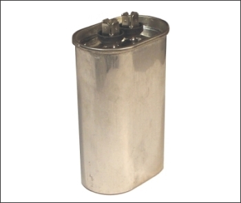
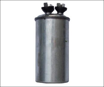
If a motor that utilizes a capacitor will not start one of the first things that should be checked is the capacitor. Capacitors must be isolated from the circuitry before being tested with a meter. Sometimes a failed capacitor makes itself obvious because it has bulged outwards. It pays to be observant. Notice the flat top on the left capacitor and the bulging outward top on the right capacitor. Click [Next] on the right to see further examples. If they do not have a built in bleed resistor capacitors should be discharged with a field supplied resistor before handling. Look at the mechanical failure of the capacitor with the bleed resistor in the right image list. In the left image list you will see that it is possible to obtain a Volt/Ohm meter that can also measure capacitance. |
||
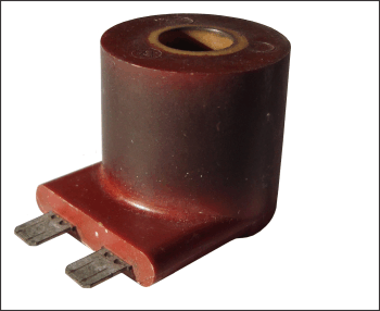
The coils of solenoid valves are electrical loads. They are energized to control fluid flow through a piping system. Heat Pumps have a 4 way reversing valve to switch modes between heating and cooling. A 4 way reversing valve is a pilot duty device which uses refrigerant pressure to slide a ported internal barrel back and forth to divert refrigerant flow. The coil is just powerful enough to open and close a small bleed port which allows refrigerant pressure to do the bulk of the work. Solenoid valves can fail mechanically or electrically. A coil can fail open or shorted or grounded. Troubleshooting can therefore requires measurements of volts, ohms and amps. It can pay to be observant. At first glance, the coil on the right looks to be in reasonable shape. However if you click [Rotate] you will see evidence of overheating. This coil was shorted. Although it would energize and allow refrigerant flow the amperage draw would steadily rise until the control circuit fuse blew. With grounds and shorts, circuits must be isolated from power and added back in one at a time until the fault is located. |
||
Heaters are electrical loads. They are easier to troubleshoot than a device like a solenoid valve because they do not have a mechanical component. They provide electrical resistance to the applied voltage and as a result give off heat to air or water. Many compressors have crank case heaters which use low wattage heaters to warm the oil in the compressor sump and prevent liquid refrigerant migration. Electric resistance heater elements must have some measureable resistance in order to to conduct electricity and create heat. An open element is obviously a failed element. However, elements can also wear out over time and still have some measureable resistance. A failing element can draw increased amperage and trip breakers or blow fuses. Most electric heater problems are due to worn out or failed controls, sequencers and even wiring. Volt, ohm and amp measurements are used to troubleshoot heaters. |
||
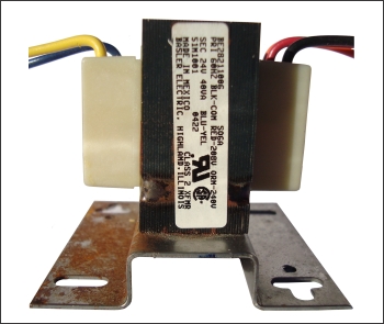
Transformers are used to step down or step up the voltage. The most common use in HVAC equipment is to step down the line voltage to a control voltage such as 24 VAC. The first image on the right is of a step up transformer used to increase voltage to 6000 volts to create a strong spark to ignite natural gas in a make up air unit. A transformers power capabilty is rated in VA or Volt/Amps. A residential furnace has small control power requirements and usually uses a 20 VA transformer. A more complicated system like a heat pump has many more control loads and may have a 40 VA transformer. Large commercial heat pumps may have 2 or more separate transformers. The secondary winding of a transformer is usually protected by a fuse or circuit breaker. If a control component fails it should blow a fuse or trip a breaker, not cause the secondary winding to burn out. If there is primary voltage to a transformer but no secondary voltage (upstream of any fuse or breaker) it is faulty. Measure the resistance of the windings to confirm that a transformer is faulty. Just like motor windings, a transformer may fail open, shorted or grounded. |
||
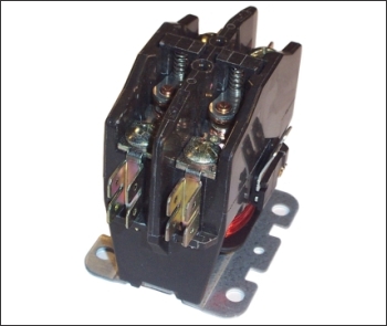
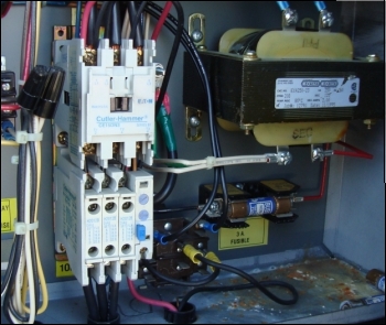
Contactors are load switching devices. Contactors are typically used to switch heavier loads than relays and have more powerful closing force than relays and therefore less contact bounce. Contactors have 1, 2, 3 or more sets of contacts and are pulled in when an electro-magnetic coil is energized. Don't assume that all contactor coils operate with a low control voltage. There are 24 VAC, 120 VAC and 208/230 VAC contactor coils in use. When a control voltage energizes the coil, the contacts close in and make circuits to line voltage loads. Some contactors have sets of auxilliary contacts which are NC and open when the contactor pulls in. An example of this is a compressor wired through the NO contacts and a crankcase heater wired through the NC contacts. The crankcase heater is needed for the off cycle but not needed for the on cycle. A contactor is composed of switches and a coil so volts, ohms and amps can be used to diagnose them. They can also fail mechanically. Although it is a rare occurance, the closing mechanism can jam open or closed. The most common type of failure is burnt contacts. Starters have overloads, contactors do not. Unlike fuses and breakers whose purpose is to protect the wiring system, a starter has an overload device which is designed to protect a motor. The overloads are selected or set to just under the full load amp rating of the motor. If for any reason that amperage is reached the overload will open the control circuit to stop operation. |
||
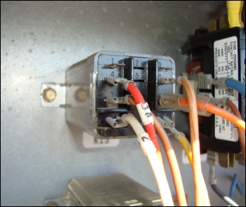
Relays are sometimes used as medium sized load switching devices but are more commonly used in control circuits. Relays are typically used to switch lighter loads than contactors. Relays can have several contacts and many have multiple sets of NO and NC contacts. Relays normally last much longer than contactors as they usually switch lighter loads. Relays can sometimes be difficult to troubleshoot. Like contactors, they are themselves a combination of a load and switches but can have many more contacts to troubleshoot. |
||
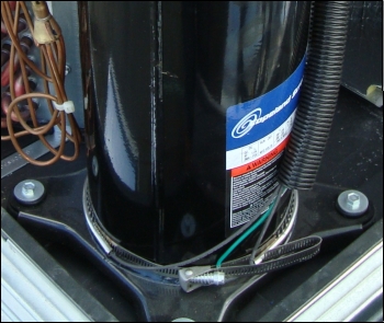
If a motor that utilizes a capacitor will not start, one of the first things that should be checked is the capacitor. If the capacitor checks out and there is proper voltage to the motor terminals then you must "ring out" the motor windings. Windings should have an MR or Measureable Resistance. If you get an open reading then you must allow time for reset of an internal overload if it has one. The windings must also not have zero resistance to ground. (grounded windings) If they do then the motor must be replaced. Shorted windings are a different problem. The windings will still have some measureable resistance but it may not be obvious if it is a normal reading or not. Amperage draw will be the deciding factor. A motor can draw increased amperage from high external loads, seizing bearings or winding faults. Bearings normally keep the rotor perfectly positioned in the center of the field windings. If bearings are excessively worn, the rotor may be positioned just enough out of true center that it will fail to start. If a motor fails to start for any of the following reasons; worn bearings and off center rotor, faulty capacitor, faulty windings or physically seized, it will have the same symptom. It will make a 60 cycle humming noise and draw locked rotor amperage until either the overload opens, the fuse or circuit breaker trips or the windings burn out. The exception is the shaded pole motor. It can be stuck and draw locked rotor amperage indefinitely without burning out. If a shaded pole motor is stuck for external reasons, freeing it up may allow it to operate properly. Troubleshooting motors requires measurement of volts, ohms and amps. |
||
Temperature Sensors are made from material whose resistance changes with temperature. There are a couple of types. RTD sensors are made from pure metals. It has long been known that the electrical resistance of a metal increases with temperature. Thermisters however are made from a ceramic or polymer. The word thermister is a combination of "Thermal" and "Resistor". There are two types of thermisters, PTC and NTC. PTC thermistors have increased resistivity with increasing temperature. NTC thermistors have decreased resistivity with increasing temperature. The change in resistance is used by devices such as electronic thermostats and for functions such as initiating and terminating the defrost in a heat pump, determining the appropriate number of heating stages and controlling the mixed air temperature in an economizer. The resistance of a thermister can be measured with an ohm meter but the information is of no use unless you have access to a temperature/resistance chart for the specific thermister. Sometimes a chart is supplied by the OEM in the equipment installation manual. The sensing device at the end of the lead of an electronic temperature meter is a thermister. |
||
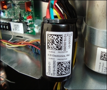
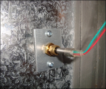
The device on the left is a surge protector. It's purpose is to protect electrical components from electrical surges. It is a MOV and is composed of metallic-oxide grains separated by insulating layers. A voltage surge breaks down the insulating layers, lowering the overall resistance which causes the device to draw too much current. This trips the breaker or blows the fuse thereby protecting the equipment. If the breaker trips for a unit with a surge protector, the simplest test may be to temporarily remove the surge protector, reset the breaker and see if the problem goes away. Gas Valves can have single stages, multiple stages or be modulating. Troubleshooting requires use of a volt meter as well as a manometer so that gas pressures can monitered when the valve is energized. Sequencers are time delay devices. They are commonly used in electric furnaces to sequence on electric heater elements in stages. Heating elements have large amperage draws so the idea is to bring the elements on in stages rather than bring them on all elements at once. They use control voltage to warm up a tiny heating element within the sequencer. A bi-metal thermodisc takes time to respond to the increase in temperature before warping closed and making a circuit. Sequencers usually contain a stack of thermodiscs which provide multiple circuit delays. There are also electronic sequencers in use. They can also be used to delay bringing on blower fan in a gas fired unit. Troubleshooting can be done with volts, ohms and amperage sensing instruments. |
||
Electronics are used extensively in the HVAC field. Electronics can monitor and/or manipulate time, temperature, humidity, amperage, voltage, phasing, liquid, CO, CO2 and perform complex logic functions. Consider a demand defrost control board for heat pumps. A demand defrost has a time/temperature initiation and a time/temperature termination. In other words a minimum time period must elapse before a trial for defrost is allowed. At that time a cold enough temperature must be present in the outdoor coil before defrost is allowed. If defrost is allowed, it may not exceed a defined amount of elapsed time. If a warm enough temperature is achieved before the maximum allotted time, defrost will terminate early. These sorts of logic functions greatly increase energy efficiency. Logic functions are much more difficult to accomplish with electrical-mechanical controls and not all logical aspects accomplished electronically are even possible with electrical-mechanical controls. Troubleshooting of the internal workings of electronic controls is not performed in the field. Rather, electronic controls are diagnosed by monitoring the input and/or output signals. To do that one must understand the purpose of the control and what it is supposed to output with a given input. An electronic thermostat uses temperature as an input. If the temperature drops, the control should output a call for heating. If the temperature rises it should output a cooling call. These functions can be accomplished by a mechanical T-Stat but a mechanical T-Stat cannot be programmed to set back automatically at night and recover the space temperature before the occupied time period starts. Here is an example of the need to understand the required output from an electronic device. A FFK filters a T-Stat signal in the following manner. If a call for 1st stage heat is received it allows heat pump operation. If a call for 1st stage heat and 2nd stage heat is received it filters the input signal and only outputs a call for 2nd stage heat. This logic is required to insure that a heat pump and a fossil fuel furnace are not allowed to operate simultaneously. So troubleshooting electronic devices requires not just the ability to find the control voltage common and measure output signals but the knowledge to interpret them and determine if the control is doing what it is supposed to do. |
||
Three Phase motors require a balanced power supply. Never operate a motor where the supply voltage has more than a 2% imbalance. Use the Voltage Imbalance formula shown below to determine the percentage of voltage imbalance. If the Voltage Phase Imbalance is more that 2%, contact the utility company. If you forget how to calculate percentages click this button. |