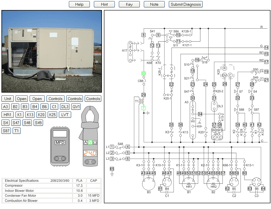
Packaged Conventional 2H2C - Board 20

| Diagnose equipment problems with virtual test instruments. Electrical measurements can be taken at any of the test points on the electrical schematic. Test and improve your troubleshooting abilities with realistically portrayed equipment faults. The above screen shot indicates features with circled red numbers. Click the circled numbers to go directly to the corresponding explanation. You can also click on any of the circled numbers by the explanations to return to the screen shot. |
 |
The Volt/Ohm/Amp meter can be used in any of it's three modes. |
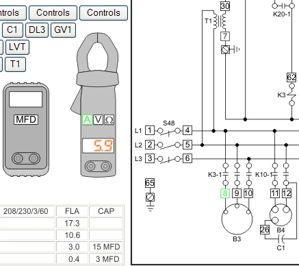
| If the Amp button is clicked it will turn green to indicate that the meter is in Amps mode. Any test point on the schematic may now be clicked and the meter will display the amperage draw at that point. The mode button and the currently selected test points turn to green. When the meter is in amps mode and you click a test point, the amperage draw of all the loads in that electrical branch are displayed in the meter. If there are "sub branches" those loads are included. |
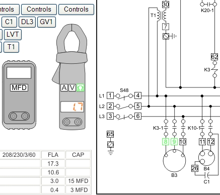
| If the Ohms button is clicked it will turn green to indicate that the meter is in Ohms mode. Any two test points on the schematic may now be clicked and the meter will display the Ohms between those two points. If you select test points that are far apart you are likely to get an alert window stating that there are too many resistances to be meaningful. If you wish to know the resistance of a component select the two closest test points. The power in an electrical circuit must be turned off before using an ohm meter. If you fail to do so you may damage the ohm meter or at least blow the meter's fuse. Anytime you put the meter into ohms mode it is assumed that the power has been turned off. To measure the resistance of a component select the 2 closest test points. It is assumed that any parallel loads have been taken out of the circuit. If you try measuring a circuit with several loads in parallel or series you are likely to receive the following alert: |

| In real life you will have an ohm reading representing the combination of all the series and/or parallel resistances between the 2 test points you selected. However those types of readings are seldom useful when troubleshooting. That is why you must isolate components from the rest of the circuitry to take a resistance measurement. You may still attempt any measurement you wish and are not restricted to adjacent test points only. When it is somewhat obvious that a specific component or wiring circuit is being tested you are likely to be given a reading. The further apart your test points are, the greater is the likelihood that you will receive the above alert instead of a meter reading. When you take a reading that has direct continuity (zero resistance) between 2 test points and there also happens to be a measurable resistance in parallel, the measurable resistance load is ignored. This is true in real life as well as in these troubleshooting boards. That is because electricity will favour taking the route of least resistance. |
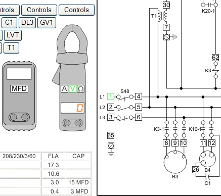
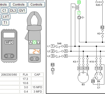
| If the Volt button is clicked it will turn green to indicate that the meter is in Volts mode. When the meter is placed in the voltage mode, one test point is automatically selected. This is typically L1 or L2. You may now select a second test point with the mouse cursor and the meter will display the voltage potential between those 2 points. A volt meter reports a voltage potential across an open circuit and across loads. If you wish to use a different default test point, click the volt button again and the next available test point will turn green. Remember that you can click the Note button while you are getting accustomed to the user interface. |
| Here is an example. Let's assume that you wanted to measure the voltage output from the control voltage transformer. To do that you would need to click the V button four times until default test point 7 was selected and illuminated green. Then clicking test point 30 with the mouse would cause the volt meter to display 24 VAC if the transformer was working properly. This control circuit has a grounded common for the transformer. You could therefore obtain the same measurement by using test point 65 (ground) as the default test point. |
| The following chart keeps track of your progress through the 100 troubleshooting boards. Your browser highlights the numbers as visited links. You can click on the board numbers to return to the last board you were working on. The Help button on every board opens this page so that you can refer to the progress chart at any time. The green links are available for browsing. |
| 1 | 2 | 3 | 4 | 5 | 6 | 7 | 8 | 9 | 10 |
| 11 | 12 | 13 | 14 | 15 | 16 | 17 | 18 | 19 | 20 |
| 21 | 22 | 23 | 24 | 25 | 26 | 27 | 28 | 29 | 30 |
| 31 | 32 | 33 | 34 | 35 | 36 | 37 | 38 | 39 | 40 |
| 41 | 42 | 43 | 44 | 45 | 46 | 47 | 48 | 49 | 50 |
| 51 | 52 | 53 | 54 | 55 | 56 | 57 | 58 | 59 | 60 |
| 61 | 62 | 63 | 64 | 65 | 66 | 67 | 68 | 69 | 70 |
| 71 | 72 | 73 | 74 | 75 | 76 | 77 | 78 | 79 | 80 |
| 81 | 82 | 83 | 84 | 85 | 86 | 87 | 88 | 89 | 90 |
| 91 | 92 | 93 | 94 | 95 | 96 | 97 | 98 | 99 | 100 |