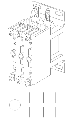
A contactor is like a large relay. Relays are generally used for switching light loads like control circuitry and relatively small motors. Contactors are used for bringing larger loads online like compressors and large motors. Contactors can have 1,2,3 or 4 sets of contacts. Contactors have NO contacts but can also have auxiliary contacts which can be NO or NC.

The buttons demonstrate how the contacts pull in when the coil is energized. The schematic symbol also toggles showing the contacts in the open and closed conditions. Contactor coils are available in several voltages, for example; 24 VAC, 120 VAC, 208 VAC, 230 VAC, or dual rated at 208/240. A typical use for a contactor is using a 24 VAC control circuit to switch a high voltage/high amperage load like a compressor. Some larger contactors have changeable coils.

Although the contacts snap shut quickly, arcing occurs between the contacts as they approach the closed position. This arcing eventually wears out the contacts. It is wise to inspect the condition of contacts reasonably frequently and replace the contactor before they become so pitted and burnt and carboned up that the compressor (or whatever load) is placed in danger. If contacts stick shut, a compressor can continue operating regardless of any operating or safety controls that may open. It can continue operating in the absence of evaporator and/or condenser fan motors which can cause compressor failure in short order.

.
"Starters have overloads, contactors do not". If you can remember that little phrase then you will remember the difference between contactors and starters. The 3 phase schematic diagram below shows a circuit with a starter. The starter has 3 sets of contacts and a coil just like a contactor. However it also has amperage sensitive heaters and overloads which are placed in series with the coil. If any of the lines draw more amperage than the rating of the heaters in series with the starter contacts, then the corresponding overload will open. Since all of the overload switches are in series with the starter coil, any one that opens will de-energize the coil and stop the compressor. As a matter of fact all the safeties are in series in this schematic and any safety that opens will stop the compressor.
Sometimes a manufacturer designs in a lock out circuit to protect the equipment. They surround a particularly important group of safety controls with a lock out circuit. If any safety control within the group opens, the compressor is stopped and will not restart even if the safety control resets. Press the Normal button. Note how there is no electrical flow through the LO (Lock Out) coil. This is because the lock out coil is a high impedance coil (high resistance) and the electricity takes the route of least resistance through the closed safety controls. However, if any of the controls in the group opens, the electricity has no choice other than to flow through the LO coil. Press the Lock Out button and see this happen when the HPC opens. The LO coil becomes energized and it's NC contacts open. This forces the LO coil to remain energized which stops electrical flow through the group of safety controls and keeps the compressor off.

Note that when the system is locked out, there is a circuit through two loads in series. (the LO and CC coils) The CC coil has a low impedance and requires more amperage to energize than does the high impedance LO coil. When the LO coil is energized it drops the voltage so much that there is insufficient power to energize the CC coil. The windings in the CC coil are in effect just acting as a conductor to complete the circuit for the LO coil.

A lock out forces attention to a problem situation rather than allowing the equipment to cycle indefinitely on a safety control and perhaps go unnoticed until damage occurs. Interrupting the power will reset the lock out if the safeties are reset. However, if all the controls in a lock out group have reset it is not possible to tell which one caused the lock out. An inspection of the equipment may reveal the cause. For example a dirty condenser might indicate that the HPC had tripped and reset after the high pressure condition subsided (while the system was off).

If there are no visible indications there is a trick that can be used to determine which control is opening. Wire a very small capacity fuse (1/10 AMP) in parallel with each of the safety controls. As long as nothing trips the electricity will once again take the route of least resistance through the series of closed safety controls. However as soon as one of them opens, the electricity will attempt to flow around the open control through the fuse which will blow instantly due to it's extremely small rating. The next time the equipment is inspected it will not matter if all of the safeties in the lock out group have reset. The fuses can be Ohmed out and the one that is blown will indicate which safety opened.

[The full version carries on with transformers, oil failure controls, humidistats, defrost timers, fan delay stats, termination stats, bi-metal controls and low voltage controls]