 |
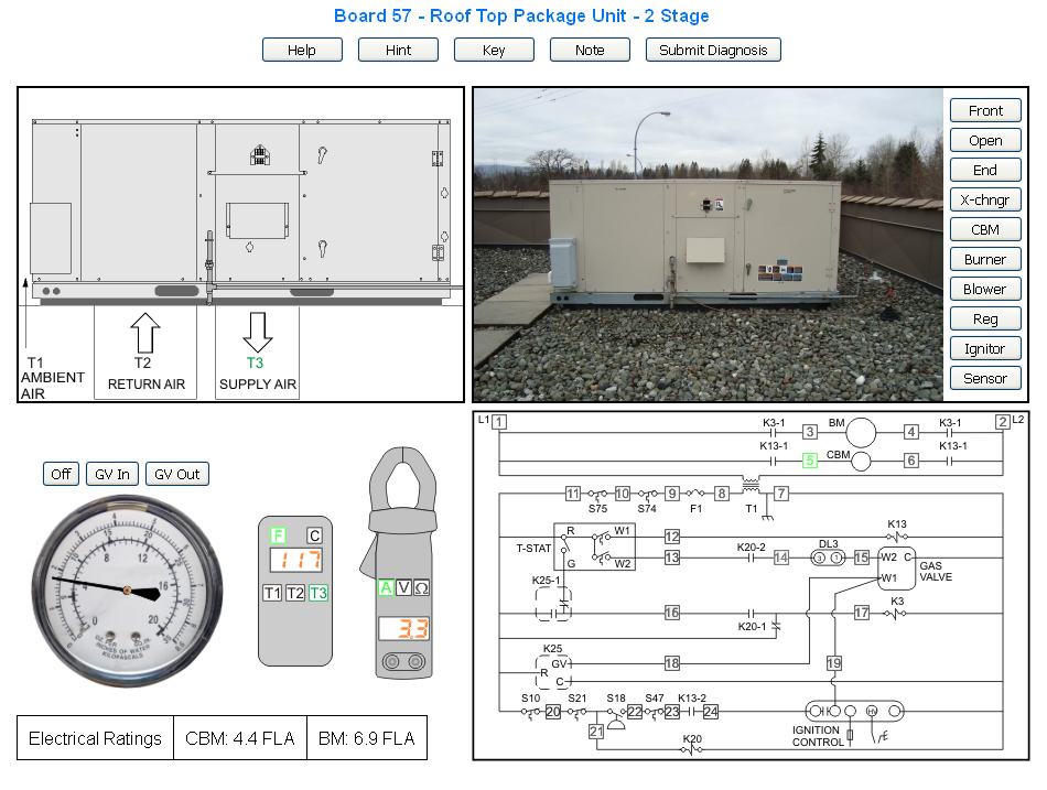
There are 100 troubleshooting boards. The title references the board number and informs you which equipment type that you will be diagnosing. |
 |
The Help Button opens this help page in a new window and is available from any of the troubleshooting boards. |
 |
The Hint Button sometimes provides clues such as might be given by the equipment owner. |
 |
The Key Button opens a window with a list of definitions of the key words or acronyms used on the page. |
 |
The Note Button brings up a message explaining the use of the Volt meter on systems which utilize multiple voltages. (Line voltage and a control circuit voltage) When the meter is put into volts mode, Test Point 2 (which is L2) is automatically selected as the location for one voltage lead for high voltage measurements. Click V again to toggle the default voltage lead location to Test Point 7 (which is 24 VAC common) for low voltage measurements. |
 |
When you believe that you have correctly diagnosed the problem click the Submit Diagnosis button to open a new window where you may submit your diagnosis and find out if you are correct. |
 |
A sketch of the unit is provided showing ductwork and temperature test points. Section (11) explains how to use the temperature meter. |
 |
When a temperature test pont is selected from the temperature meter, that test point changes to green on the layout sketch. |
 |
You may click on these Buttons at any time to see various views and components of the equipment that you are troubleshooting. |
 |
Click the Buttons to measure the gas pressure at the GV (Gas Valve) inlet and outlet. |
 |
This is your digital thermometer. The three temperature buttons on the meter T1, T2 and T3 correspond to the three test points on the sketch (7). Note that the T1, T2 and T3 test points on (7) turn to green when they are selected. |
 |
The Volt/Ohm/Amp meter will display a reading of any test point on the schematic. All you do is click on the test point. First however, click one of the buttons on the meter to indicate whether you wish to measure Amps, Volts or Ohms. The test points on the electrical schematic turn green when clicked on. If you select Amps,(A) you may click on any test point on the schematic to view amperage draws. If you select Volts, two test points will be required in order to measure the voltage potential between them. If you select Ohms you must click on any two test points to measure the resistance between those two points. All Ohm readings are taken with the power off. (The power is turned off automatically) Keep this in mind if you are measuring something like a PD Switch. (It will automatically be open when the CBM is inoperative due to the power being off) If you select two test points surrounding a component, that component is automatically isolated from the rest of the circuit for your resistance measurement. If you try to measure the resistance of multiple components you will receive an error message: |

| Electrical Measurements - Summary |
| Amps |
When the meter is in amps mode and you click a test point, the amperage draw of all the loads in that electrical branch are displayed in the meter. If there are "sub branches" those loads are included. |
| Volts |
When the meter is placed in the voltage mode one test point is automatically selected. This will be Neutral, Line 2 or the common of a control circuit. You must select the 2nd test point. The volt meter then displays the voltage potential between those 2 points. A volt meter reports a voltage potential across an open circuit and across loads. Note that when in Volts mode, the L2 leg (or Neutral) turns green automatically indicating that one of your leads is pre-selected for you. All you need do is select the other test point that you wish to take a reading from. On diagrams with both line voltage and a 24 volt control circuit click the Volt button on the meter a 2nd time to change the pre-selected lead to the 24 VAC common. |
| Ohms |
The power in an electrical circuit must be turned off before using an ohm meter. Anytime you put the meter into ohms mode the power is turned off automatically. To measure the resistance of a component select the 2 closest test points. It is assumed that any parallel loads have been taken out of the circuit. If you try measuring a circuit with several loads in parallel or series you are likely to receive the above alert message. |
|
 |
The FLA ratings of motors are given so that you may compare the actual measurement to the rated amount. |
 |
The electrical schematic has test points for taking electrical readings. |
 |
The test points on the electrical schematic change to green when they are selected. |

